As we reach the deadline, the two of us are getting closer on reaching our goal. As of now we have currently four different programs created through processing. Each adds there own sense of creativity and interactive surprise. We have one program that has moving stars, one being a 3D roaming space, floating squares, and a reflective drawing program. Not to mention, each of them will be programmed with a unique music that fits the art. Our goal is to find a way to operate the programs through Arduino, however, the process is quite challenging as we are tring to cooperate it to work with more than one knob. Before Wednesday, we will test our programs through syphon and mad mapper to get our final product. By looking through out the campus we have narrowed down our decision on which where we will be projecting are works of art. Our option is to project the art behind Wilson Hall, however if the weather is not looking well on Wednesday we have considered the Pollock building near the stairway. Hopefully, by the time of our final we will have a fully multi interactive work of art for everyone to enjoy.
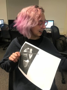
So last class we continued working on building our zine, some more cutting, glue, etc. We built our front and back cover, and in that moment Commit 2 the Bit felt real!! We all came together with greaat ideas, but it was time for some Yes, and.. that we learned from Chris Clavio, and began creating a meta layer for our zine. What is going to be taken away from the zine by the reader? What will layar allow us to give the people in addition to our publication? That was a big question for us but I believe we are solving it without even thinking too hard.
We are all college students! Our zine begins to take on the brain of a student in the final weeks of school. The stress, the raw emotions, which in itself is so punk rock! That is the zine, punk rock rawness of three college students. That is what is so awesome about layar, it allows us another platform in addition to the paper zine to influence our readers. We will have music, animations, links, voting polls, all embedded within.
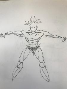
I learned more about After Effects and am currently making some animations for my pages to add to the experience. A little stressful but this animation (1) turned out better than my first week’s animation (madmapper) and I cannot express how great it felt to improve my skills. Here goes animation 2 to be better than the first!!!
I am so so excited to see the final turnout of the zine. It looks so awesome now I can hardly imagine how awesome the whole zine experience is going to be!!!
This past week has consisted of engaging in the initial stages of conceptualizing different ideas for the final project, and narrowing them done to one that we want to commit to. My partner Alexa and I, knowing that our end goal is to present a proof of concept, began by writing down different ideas in our journals. We knew we wanted to do something with projection mapping, but at first, we weren’t exactly sure what. As we brainstormed, we kept the mentality of “no idea is a bad idea” We tried not to think about the logistics in the beginning, because we didn’t want that to hold us back. This worked in our favor because both of our ideas were bouncing off each other, until we came up with an idea that we were both excited about and would work best for us.
We are looking to create a documentary style/ manifesto video combining b-roll, and projection mapping. The theme that we will be going with is using Alan Watts’ motivational speeches/quotes to combine the footage and overall message. We’re interested in showing the behind the scenes work that it takes to setting up the projection, along with video clips as b-roll that support the theme. We hope to use the smart beam laser, as its versatility will allow us to use multiple locations and projection techniques that will be filmed. Our end goal is to create an inspiring video that combines the worlds of art and technology.
I think one of the important aspects of starting a project like this is to keep an open mind. It’s impossible to flesh out every aspect of an idea in one sitting, especially the first time. Working with a partner is helpful because there’s two brains working together to think of ideas, fill in the blanks, and make progress. Knowing we only had 2 weeks to create our project has been a little daunting, but I think the challenge has so far pushed our creative minds in new and exciting ways.
For my final project, I decided I wanted to make something that would transport the audience or consumer to another place. In New Jersey, we have been subjected to a lot of inclement weather, when what most people really want is a nice day to relax outside or on the beach. With the weather that we’ve been having, this is quite impossible to do unless you want to be freezing your butt off. To transport the viewer to a new place, I plan to use a couple things.
First, I am creating a print of a dreary, snowy landscape. I am doing this in photoshop. Here is what I have worked on so far:
This print will be displayed in the lobby of Plangere. This will be done with a projector onto a wall when you first walk in. This will catch the attention of many people. Once people see this, they will be able to scan the print using Layar. When scanned, the print will take you to a website containing a 360 video of a beach landscape. This is the video I am planning to use:
Doing this will allow for the user to escape this bleak landscape that we are in, especially during finals week, and be transported to a beautiful place where you can relax for a bit.
For our final project, Nick and I have decided to push along an already developed idea created by Nick. “Red Hot!” as it will tentatively be referred to, is a user interface that uses software processing and an Arduino board to feed back information to the computer. The appearance on the outset looks relatively simple; a simple green background, with a percentage bar at the bottom (starting at 0%). In order to raise that bar to 100%, people will have to use Arduino board components to dial in a response. When people do manage to reach 100%, the color of the background shifts to red, with a sign “RED HOT!” appearing, along with a voice-over exclamation repeating that same phrase.
The first week consisted of an overview of the entire project, which Nick did a walk through of during class. The original material began with developing a code in Processing 5. Much of the Processing material involved the look of the actual project, as well as Booleans, which would allow for the switch from the calmer backdrop to the redder, more scary one (RED HOT!). That code was then brought over to Arduino, where he further developed the project to intermingle with the actual Arduino and breadboards (switchPin’s and ledPin’s, inputs and outputs, things of that nature). **NOTE: We are currently trying to incorporate more external pieces, which, I’m assuming, you could just refer to as “eye candy”. But eye candy is nice–and it was also something we took time doing for the second half of class.
Following Jeremy Blum (incredibly awkward dude–great sense of humor though. He’s also got a humongous breadboard, bless him), we were able to properly set-up input and outputs to assigned jumper wires connected from the board, to the Arduino itself, and then to the computer. After some trial and error, we were able to incorporate newly placed LED lights, to light up the breadboard, as the actual interaction was happening. The LED lights would be controlled by an alternate button. The main input device within the project, and found on the breadboard, is the pentotimeter, which directly controls the interaction of “Red Hot!”, along with the percentage bar going to 100%, and the color changing.
This is a page taken from my notebook, where Nick was detailing just how the pentotimeter functions, and where the dialing values stand. On a 0-8 scale, each number expands immensely, even if the increase was by 1 digit. It is only possible to have whole numbers; decimals are not really possible. The 0-8 scale represents the dialing of color in processing, where 0 is of course 0, and 8 is 255 (the maximum shade of red you can reach in this case).
Throughout this week, we are currently tasked to find other tools we can operate on with the Arduino and breadboard. So far, no new ideas have popped up. At this point, no idea sounds too crazy at the moment. Must provide update later in the week, if there is a sudden light bulb going on (not an LED one, and no 10k resistor busting it either).
Hey all. I hope you’ve all had a good first week with our final project.
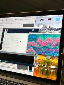
Since our last meeting, we has really begun to take form. Our plan is to have an enclosed space that we can project the upper half of with a visualizer. So far, we have three codes that we either appropriated from an open forum or made with tutorials, there’s one more that we have in the works that I’m doing research on. It was an interesting experience coming upon these scripts. Even when we were taking something that someone else made, there was still a good amount of work changing it so that it would run on our system. The job then became tailoring it to our needs turned out to be a surprisingly labored process. Our next step is to learn how to insert the arduino commands int0 this code so that a user can take control and change the environment. Tomorrow, our plan is to go scouting for locations on campus to house this installation. We were thinking about looking in the Reichnitz building, as well as the basement floor of the ice house gallery. I seem to remember a past gallery had a projector installation down there, and it seems like an ideal location for that type of thing. It does depend on if the gallery space is being used already or not, so this is all stuff that we’ll find out tomorrow. Also, we wanted to incorporate music into this project and so I’ve compiled a short list of possible songs for each “mode”. I think each program has its own feel and the music should reinforce that.
Again, this project in two weeks is a daunting task, but beyond that, I think the tight time restraint gives the project a certain sense of spontaneity and I think in the end it can really benefit. It all comes down to how we deal with that constraint.
So that’s what we’ve got right now, and what we have in the works.
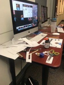
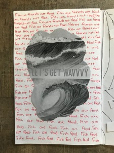
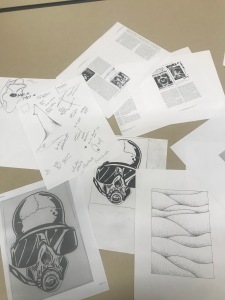
So for this week our group for the final project, Anne, Ali, and Jeylin, have been making our zines!! Cutting, pasting, writing, doodling, spilling out what we think needs to be said and passed around!!
Our zine name is Commit 2 the Bit, so punk rock, right?
Each of us has four pages we are working on, and we are thinking about which elements on our pages we want to make interactive on layar. Next time we meet in class we will make the pages interactive and have certain elements link to websites, music, and more!
I attached images of the process so far. This had been such a fun project so far because I am becoming more aware of QR codes in advertising, and how I never used them and I rarely see them being activated. I think layar and other interactive modes of connecting print media to our phones and the internet is the new wave of influencing viewers!
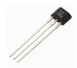
A Hall effect sensor is a transducer, which shifts its yield voltage in response to a magnetic field. These sorts of sensors are utilized for proximity awareness, detection of speed, and use of other sensing programs. To sum, it works like a simple transducer, therefore redirecting the voltage back to start. Its separation from the Hall plate can be resolved with a known attractive field. By utilizing gatherings of Hall effect sensors, the relative position of the magnet can be resolved. The power, which is helped by a conductor, will create an attractive field, which shifts as indicated by the current. The sensor can accordingly be utilized as a part of a request to gauge the current without intruding on the circuit. The sensor is regularly incorporated into a lasting magnet or an injury center that encompasses the conductor to be estimated.
The US1881 is an incorporated Hall impact locked sensor. It holds the magnet close to the sensor in order to the transmitter to stick to flip. This makes for a vigorous nearness sensor. An inner band gap controller is utilized to give temperature repaid supply voltage to interior circuits and permits a wide working supply to extend.
The price for the HES ranges from two dollars up to thirty, depending on store and brand. The HES can be purchased online from electronic stores.
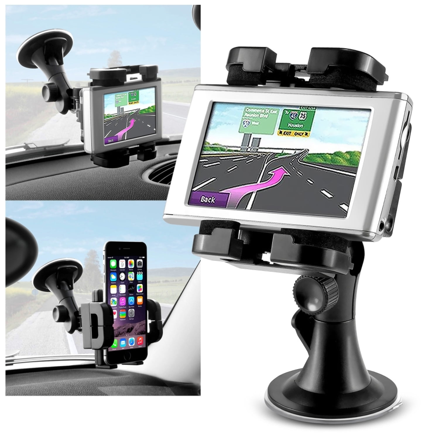
GPS, also known as Global Positioning System, can often be found as a built in accessory to our smartphones, motor vehicles, or even sold separately as attachable/portable GPS navigation systems.
Considering this is a widely known tool to our society today, a historical background on the device’s manufacturer’s model is necessary in order to understand the development on its implementation in a lot of today’s technology.
For starters, on nasa.gov (https://www.nasa.gov/directorates/heo/scan/communications/policy/GPS_History.html), they provide a complete explanation on how this device has came to be and the need for this discovery. It originated with the “sputnik era” as they call it, which is the launching of Sputnik-a kind of satellite, which is how this device functions. Scientists during this time (1960s), would be able to track radio signals, also known as “Doppler Effect.” During this same era, the U.S Government found this astonishing and began to conduct experiments to find a way to track U.S. submarines. Their experiments later resulted in their ability to track satellite changes in this Doppler effect and target U.S. submarines locations within minutes! A decade later, the DoD (Department of Defense) wanted to find stabilization in satellite in order to produce a navigation system that’ll function in all circumstances. After testing this, the proposed navigation system was then powered by satellite and said scientists released NAVSTAR satellite in 1978-Navigation System with timing and ranging consolidating the power of 24 satellite systems to give these navigation systems the ability to find location in 1993. Today, GPS is a space-based radionavigation system that is owned by the U.S. government and operated by the U.S. Airforce for purposes like homeland security, defense, civil, commercial and scientific needs. This system provides 2 levels of service; (SPS) Standard Positioning Services which uses Coarse Acquisition-in other words, is available to all users continuously and on a worldwide basis. Its performance is basic and not as accurate as the second level of service, (PPS) Precise Positioning Service which uses P(y) code on Level 1 and 2 frequencies, only used within select armed forces and governments because of how great of quality this GPS provides.
This sensor locates geolocation anywhere in the world that sights four or more satellites. It is now possible to locate specific devices using this function on smartphones or select social media applications.
As this is a satellite based system, it consists of 24 orbiting satellites-making two circuits every 24 hours. These satellites transmit 3 bits of information- satellites number, position in space, and time the information was sent. These signals are then picked by the GPS receiver which calculates distance between it and the GPS satellites. With the signal from four or more satellites a GPS receiver can locate the longitude and latitude on the ground.
GPS’s can range from $25-500 depending on quality and the abilities you’d want the GPS to have. (Often sold in stores with technology departments such as best buy, walmart, target, etc.)
If you didn’t want an attachable GPS, you can also download free applications on your mobile device that offer different kinds of conveniences such as ones that target nearby traffic, gives you a wider range of routes to take in order to save time traveling, etc.
The Force Sensitive Sensor, or Force Sensor-Resistor, as it is commonly referred to, are the sensors that detect, or track, physical stress, squeezing, or weight. They are conductive polymers (controlled through electricity) which are used through the application of force, and from there, sub-micrometre sized particles are formulated and touch the eletrodes to shift and change resistance (these sub-micrometre particles are all suspended in the film layer–which is where most of the electrode resistance and sensing occurs). Typically, these sensors only garner a range of pressure, detecting, instead of approximating the exact weight. It is said that FSR’s vary from sensor to sensor with a 10% margin. Conducting electrodes that manipulate resistance usually comes as a polymer sheet or ink, and are applied with screen printing (coating areas with some substance). The Resistor Pressure is measured in Ohms: the more pressure that is applied, the lower the resistance on the actual film is.
Presented here in this picture, is the Interlink 402 Model. On the right, the 402 Model’s interior is deconstructed. Between the flexible outer material, with a printed semi-conductor field, and the electrodes is a spacer adhesive, which acts as a sort of barrier and conductive controller of electrode flow. The over sensing-region is about a 1/2 diameter, while the entire resistor itself is 2.35 in. The overall thickness of the board is about 0.73 in., while the weight is roughly 0.01oz. Force Sensitive Resistors can also come in square shapes as well, but usually amount to the same conducting force.
While using an Arduino breadboard, the best way to apply a 402 Model is simply by plugging it in. Other ways consist of using clamp-style connectors (terminal blocks), or soldering onto the tabs (Soldering is the process of joining two or more objects together, through the process of melting and applying a filler jacket into a potential “joint”). Though they are very flexible and light in weight, the 402 Model is also made of very delicate material. In fact, most FSR models are very similar in power and cost (Interlink, as well as Sparkfun Electronics, Honeywell Sensing Productivity Solutions are responsible for creating them). Typically, a Force Sensitive-Resistor costs around $7.00, can sense force applied between 100g to 10kg, and are around 2-3 inches long.
In order to test how an FSR works, you can use a multimeter to connect to the resistance-measure mode. A multimeter’s measuring abilities range from continuity, resistance, voltage, and currents. Connecting the multimeter to the two tabs on an FSR Model helps show you how much the resistance changes.
To see a more in-depth way of how these resistors work, provided here are videos that walk you through this very concept: